MFP7E20-N030 MFP7E20-N010 Twin-port NDR transceiver has a unique NVIDIA patented design enabling two, multiple-push-on/angled-polished connector 12-fiber (MPO-12/APC) optical connectors per single OSFP form-factor by turning the optical connectors vertically in the twin-port transceiver end. MFP7E20-N030 enables it to host two NDR transceivers inside, each with its own MPO-12/APC optical connector operating independently that can link to another Twin-port transceiver or to a single port 400Gb/s NDR transceiver.
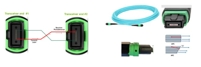
MFP7E20-N030 MPO-12 has a 12-fiber ribbon but only 8-fibers are used – four transmit and four receive fibers for the 4-channels of 100G-PAM4 NDR. The APC design minimizes back reflections and signal interference by diverting back reflected light from the fiber face to be absorbed into the fiber cladding. A positioning key on top of the connector together with the alignment pins define the fiber position numbering scheme to align pin 1 in the optical connector to pin 1 in the transceiver also called “polarity” Transceivers have alignment pins for precise positioning of the cable connector against the optical beams. The fiber cable has alignment holes matching the transceiver’s pins. It is important to note that transceivers have pins. Optical connectors have holes and are used with transceivers. Optical connectors with pins are not compatible with transceivers and are used in trunk cabling to connect two fiber cables together.
The MPO-12/APC optical connector is used in both the NDR single mode and multimode fiber cables. Multimode optics is denoted by a tan-colored pull tab and aqua-colored optical fiber. Green plastic shell on the MPO-12/APC connector denotes Angled Polish Connector and is not compatible with aqua colored shell for Ultra-flat Polished Connectors (UPC) for HDR. MPO-12/APC Showing 4-Transmit and 4-Receive Fibers and Angled Polish Connector End.
| Model number | 4-channel MPO/APC to Two 2-channel MPO/APC |
|---|---|
| MFP7E20-N010 | 10m |
| MFP7E20-N015 | 15m |
| MFP7E20-N020 | 20m |
| MFP7E20-N030 | 30m |
| MFP7E20-N050 | 50m |
MFP7E20-N030 The MPO-12/APC optical connector is used in both the NDR single mode and multimode fiber cables. Multimode optics is denoted by a tan-colored pull tab and aqua-colored optical fiber. Green plastic shell on the MPO-12/APC connector denotes Angled Polish Connector and is not compatible with aqua colored shell for Ultra-flat Polished Connectors (UPC) for HDR. MPO-12/APC Showing 4-Transmit and 4-Receive Fibers and Angled Polish Connector End.